- Entry
- 009
- Source scale
- 1:24,000
- Method
- Field measurement and compilation
- Section
- Relief
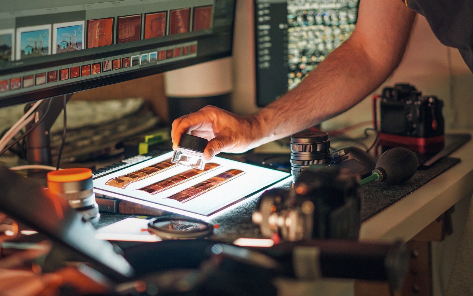
Two overlapping exposures are fused into a single model, and the operator traces relief inside it at constant height.
Photo: Jakub Zerdzicki / PexelsThe Floating Mark
Before airborne laser became routine, most of the relief on a topographic sheet was compiled at a stereo plotter — a machine that presented two overlapping aerial photographs, one to each eye, and let a trained operator read depth from the combined image the way binocular vision always does. The overlap, conventionally around sixty percent along a flight strip and around thirty percent across adjacent strips, was not accidental: it was the minimum needed for every point on the ground to appear in at least two frames taken from different positions, which is the geometric condition stereopsis requires.
The operator looked into the instrument and saw a single fused landscape in apparent three dimensions. Suspended over that landscape was a small bright point called the floating mark — actually two half-marks, one in each photograph, that merged into one when the geometry was right. The trick of stereo compilation was this: by adjusting the separation of the two half-marks, the operator could raise or lower the floating mark until it appeared to rest exactly on the terrain surface. When it did, the instrument read off the height. Trace the mark along a contour and the instrument drew that contour. The operator's judgment — whether the mark was truly on the surface or floating fractionally above a tree canopy or a building roof — was the entire quality-control mechanism.
- floating markthe adjustable point of light the operator lowered onto the apparent terrain surface to read height
- stereopairtwo overlapping frames taken from different aircraft positions, the basic unit of stereo compilation
- relief displacementlateral shift of a feature's image caused by feature height and the camera's perspective; increases with distance from the photograph's principal point
- relative orientationadjustment that removes parallax between two images so they fuse into a single three-dimensional model
- absolute orientationscaling and levelling the model against surveyed ground control points
- analytical plotterinstrument that replaced optical projection with mathematical computation, correcting distortions in real time
Orientation and Its Errors
Before compilation could begin, each stereopair had to be oriented: the model had to be levelled and scaled against a framework of ground control points whose positions and heights had been established by field survey. Interior orientation corrected for the camera's own geometry, using calibrated focal length and the precise positions of fiducial marks printed on every frame. Relative orientation removed the parallax between the two images so they fused properly. Absolute orientation tied the whole model to the ground control.
Each step carried its own error budget. Errors in control propagated through the model; a weak control network produced a model that fitted the check points well but drifted between them. In hilly ground, where the photograph's perspective displaced features laterally — the effect called relief displacement — compilation required constant vigilance: a cliff face photographed obliquely could shift its apparent base by many metres. The better instruments, the analytical plotters that replaced purely optical machines from the 1970s onward, could apply mathematical corrections for these distortions in real time, but the operator still had to read the surface correctly.
Contour quality therefore varied with terrain type. Open hillside with clear tonal gradation was readable at the instrument; dense forest was not. Under closed canopy the operator was tracing the top of a tree layer, not the ground — the same fundamental limitation that airborne laser in its last-return mode was eventually designed to overcome. Operators working forested sheets were expected to supplement their compilation with any available ground spot heights, but in practice the contours in those areas were often form lines in all but name.

Field and desk are separate operations, reconciled only where control has been established.
What the Sheet Carries Forward
The contours on any mid-twentieth-century national topographic series — Ordnance Survey, Institut Géographique National, United States Geological Survey, and dozens of equivalent agencies — were largely the product of this method. The instruments are now largely museum pieces, replaced first by analytical plotters and then by digital photogrammetric workstations that do much of the matching automatically. The skill of reading a stereo model never fully automated: current software matches pixels statistically and generates dense point clouds, but the edited digital terrain models it produces still require human review where the matching fails.
A surface has to be cut at some spacing before it can be drawn, and the spacing is chosen rather than measured.
Photo: kdadan97 / PexelsWhat the sheet carries forward from stereo compilation is an accuracy profile that is patchy in a specific way: good on open ground, degraded under vegetation, degraded again on steep ground facing away from the sun at the moment of photography. Knowing that profile is part of reading any sheet critically — understanding not just what the contours claim but what the operator could actually see.
- Open hillsidetypically compiled to stated contour accuracy
- Dense forestcontours trace canopy, not ground; often effectively form lines
- Steep ground facing away from the sunshadow and foreshortening reduce reliability
- Urban areasbuilding roofs and wall faces cause systematic displacement requiring correction